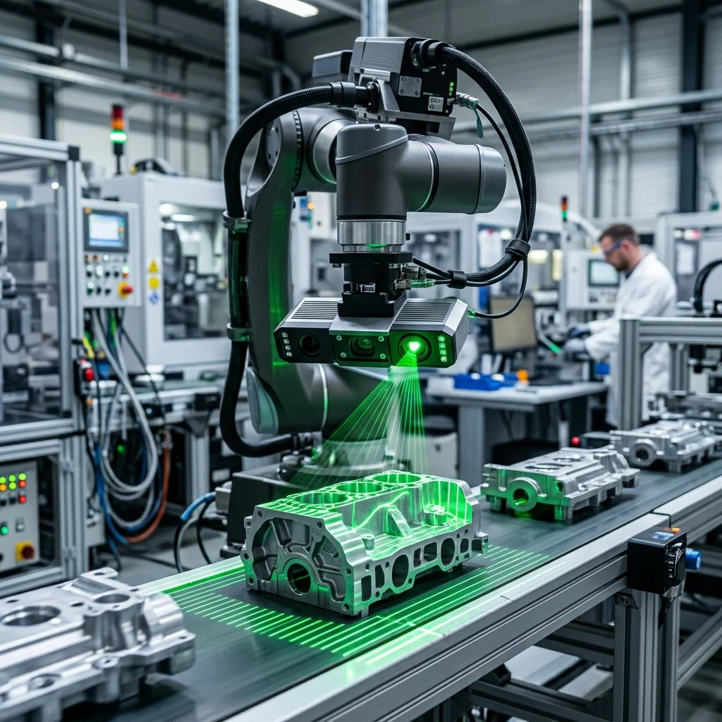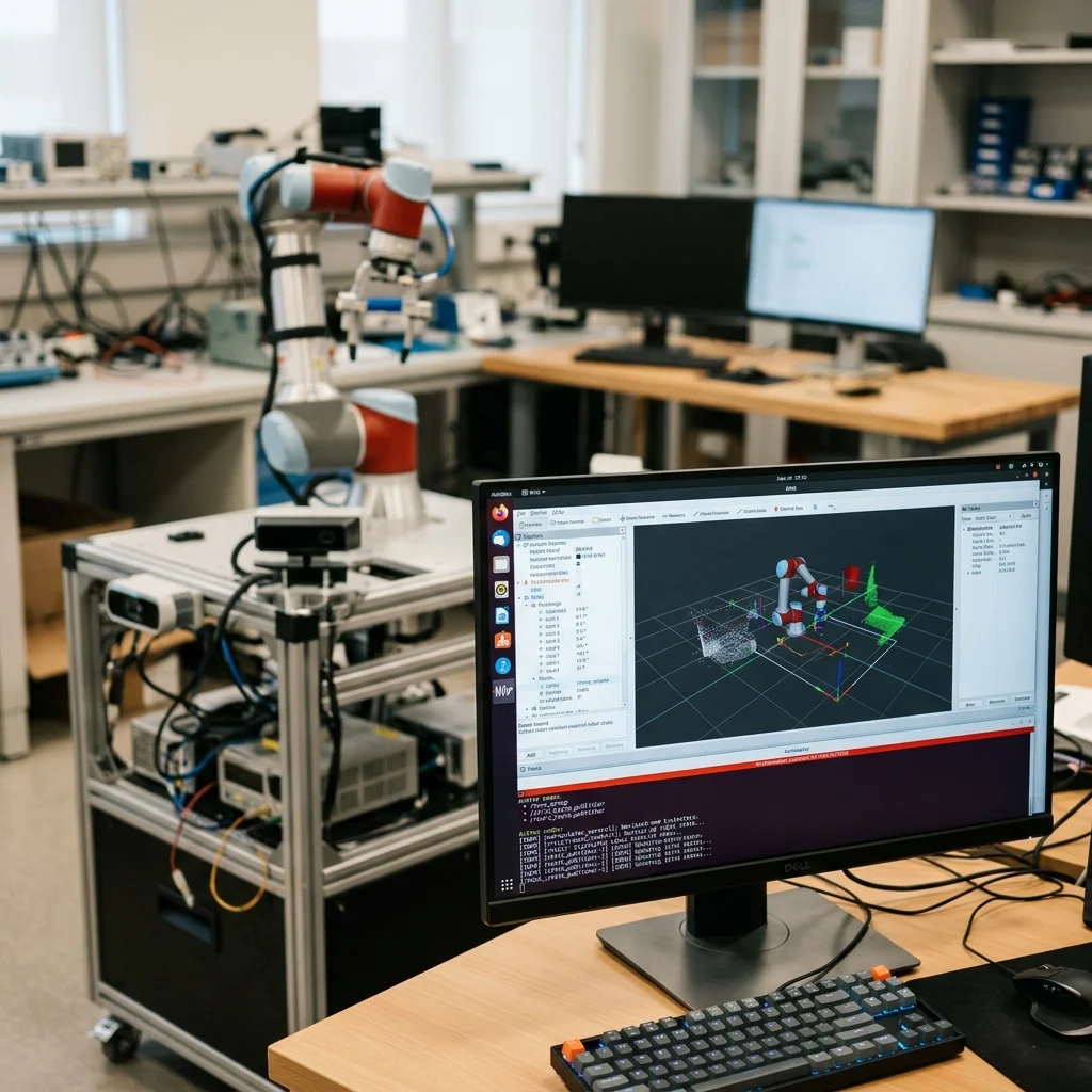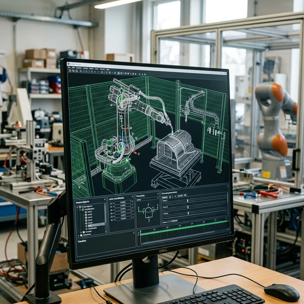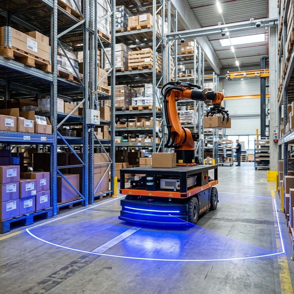
Optimizing Automated Guided Vehicles (AGVs) and Autonomous Mobile Robots (AMRs) using the ROS2 Navigation Stack (Nav2) requires tuning costmap parameters, selecting the correct trajectory planner (such as DWB or MPPI), and establishing robust LiDAR-based SLAM mapping to ensure reliable path planning and collision avoidance in dynamic warehouse environments.
The Rise of Autonomous Mobile Robots in Intralogistics
Warehouse logistics has transitioned from manual forklifts to automated mobile platforms. Automated Guided Vehicles (AGVs) follow fixed paths (like magnetic tape or wire guides), while Autonomous Mobile Robots (AMRs) navigate dynamically using onboard sensors. AMRs calculate paths around obstacles, offering higher flexibility for modern smart warehouses.
The ROS2 Navigation Stack (Nav2) has become the standard software framework for AMR developers. Nav2 provides modular packages for mapping, localization, path planning, and obstacle avoidance. Written in C++ and utilizing ROS2 communication protocols, Nav2 allows developers to build navigation systems that run on standard industrial hardware.
However, configuring Nav2 for dynamic warehouse environments requires tuning configuration files (YAML). A default installation will often fail in narrow aisles or near reflective racking. Engineers must understand how the different layers of the Nav2 stack interact to optimize path planning and prevent navigation failures.
Configuring Costmaps for Narrow Warehouse Aisles
Nav2 uses costmaps to represent the robot's environment. The global costmap is used for long-term path planning across the entire facility, while the local costmap is used for obstacle avoidance in a small window around the robot. Costmaps consist of layered grids where each cell has a cost value indicating the proximity of obstacles.
A common issue in warehouses is navigation failure in narrow aisles. If the costmap's inflation radius (the safety zone around obstacles) is set too high, the costmap will show the aisle as completely blocked, and the robot will refuse to enter. Conversely, setting the inflation radius too low increases the risk of collisions with racking.
To resolve this, engineers must tune the inflation layer parameters in the configuration file. Specifying the inflation decay curve allows the cost to fall off gradually as the distance from the rack increases. This configuration creates a safe path down the center of narrow aisles while keeping the AMR moving smoothly without triggering safety stops.
Selecting Trajectory Planners: DWB vs. MPPI
Once a path is generated, the controller plugin translates it into velocity commands (linear and angular speeds) for the robot's wheels. Nav2 supports several controller plugins, with the DWB (DWA Basic) planner and the MPPI (Model Predictive Path Integral) controller being the two most widely used.
The DWB planner uses the Dynamic Window Approach to evaluate local velocity commands over a short time window, choosing the trajectory that minimizes distance to the path and avoids collisions. DWB is computationally lightweight and works well for standard differential-drive robots, but it can struggle with complex kinematics or fast obstacle avoidance.
The MPPI controller uses model predictive control principles to simulate thousands of candidate trajectories in real time using GPU acceleration. This allows MPPI to handle non-linear dynamics, slide along walls, and navigate dynamic environments with high efficiency. For industrial AMRs carrying heavy payloads, MPPI provides smoother control and better path tracking.
LiDAR SLAM, AMCL Localization, and Reflective Environments
AMRs rely on LiDAR sensors to map their environment and locate themselves. During setup, the robot builds a map using SLAM (Simultaneous Localization and Mapping) algorithms. In production, the robot compares its live LiDAR scans against this map using AMCL (Adaptive Monte Carlo Localization) to estimate its coordinates.
Reflective surfaces, such as polished concrete floors, steel columns, and stretch-wrapped pallets, present a challenge for LiDAR sensors. Reflections can create ghost obstacles or cause sensor beam dropouts, leading to localization drift. If the localization error exceeds a set threshold, the robot will stop to prevent navigation failures.
To mitigate this, programmers must filter the laser scan data. Setting maximum range limits in the sensor filters discards reflections from distant racks. In addition, combining LiDAR data with wheel odometry and IMU (Inertial Measurement Unit) data using an Extended Kalman Filter (EKF) provides robust localization, keeping the AMR tracked even if LiDAR scans are temporarily corrupted.
AMR Navigation Tuning and Testing Checklist
Before deploying a mobile robot on a live warehouse floor, the mechatronics team must execute a systematic navigation tuning checklist. First, calibrate the wheel odometry to ensure the robot's physical movement matches the encoder telemetry within 1%. Second, verify that the safety zones configured in the lidar sensor match the costmap settings.
Third, test the costmap configuration in the narrowest aisle, checking that the robot plans a path down the center without stopping. Fourth, verify that the recovery behaviors (such as spinning in place to clear costmaps) are configured safely to prevent the robot from hitting racks. Finally, test the localization stability near reflective pallets to verify the EKF filter settings.