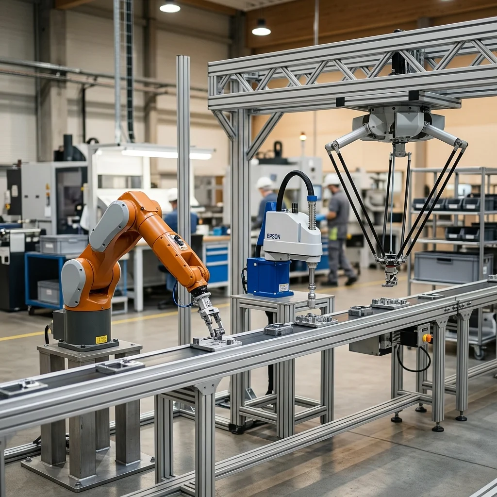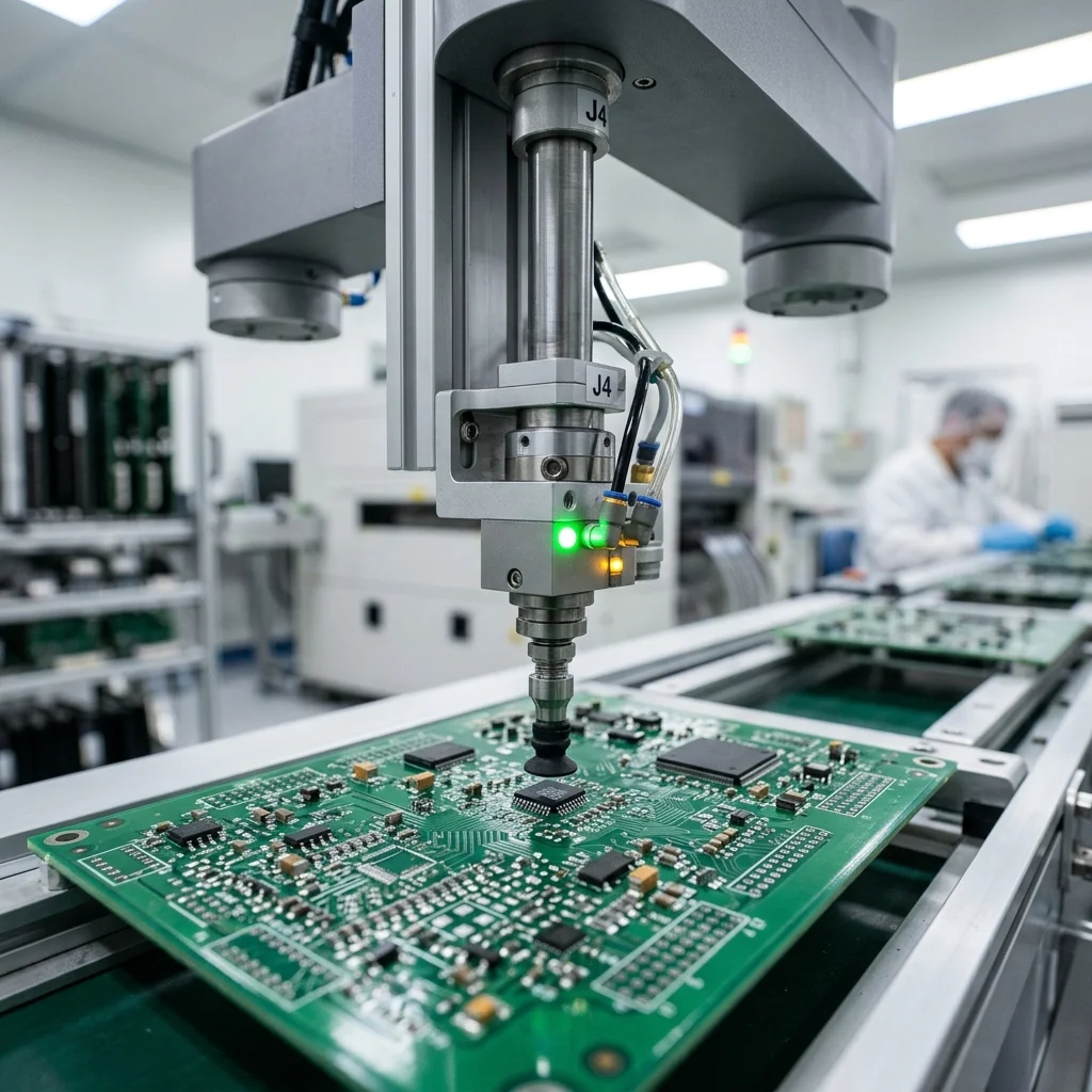
Programming Selective Compliance Assembly Robot Arms (SCARAs) for high-speed electronics assembly requires optimizing the Adept cycle path to minimize vertical (Z-axis) Quill travel and configuring planar (X-Y) joint acceleration. Utilizing soft-landing algorithms and vacuum force monitoring is essential to verify delicate microchip insertion tolerances without fracturing fragile printed circuit boards (PCBs).
SCARA Kinematic Advantages in Planar Assembly
Selective Compliance Assembly Robot Arms (SCARAs) feature a four-axis design that offers high rigidity in the vertical direction while remaining compliant in the horizontal plane. This mechanical compliance is useful for high-speed assembly tasks, as it allows the joints to adjust to minor misalignments during component insertion. This prevents pins from bending and parts from jamming during fast cycles.
Programming a SCARA requires a different approach than programming a standard 6-axis articulated arm. Because a SCARA is limited to four degrees of freedom (X, Y, Z, and Theta rotation), path planning is mathematically simpler, resulting in faster processing times. This allows the controller to update joint trajectories at high frequencies, which is key to achieving repeatable, high-speed movements.
In mechatronics assembly, every millisecond counts. SCARA paths are typically structured around the 'Adept cycle,' a gate-like motion profile where the robot lifts vertically, translates horizontally, and descends into the target location. Optimizing this cycle requires tuning the transition blends between the vertical and horizontal segments to keep the motion smooth and prevent mechanical vibrations.
Path Optimization and the Adept Cycle
To achieve cycle times under 0.4 seconds, programmers must minimize the vertical stroke of the Z-axis Quill. Every millimeter of extra vertical travel adds travel time and increases wear on the ball screw. The horizontal translation should begin before the Quill has reached its full vertical lift, creating a smooth, arched trajectory rather than a sharp, squared path.
Modern controllers (such as Epson RC+ or Denso WINCAPS) feature built-in optimization tools that calculate these transition curves automatically. Programmers must set the 'Arch' parameters to match the height of surrounding obstacles. Defining these arcs correctly allows the robot to clear barriers with minimal vertical displacement, maximizing speed.
Acceleration and deceleration profiles (also called S-curve ramps) must be tuned to prevent overshoot. If a joint decelerates too sharply, the inertia of the end effector will cause the robot to vibrate at the stop point. The robot must wait for these vibrations to settle before releasing the part, which slows down the cycle. Tuning the joint stiffness and damping values helps to eliminate this settling time.
Precision Insert Tolerances and Soft-Landing Control
Placing delicate silicon components or connector housings requires tight tolerances, often within ±0.02 mm. Standard position control can apply excessive force if a part is slightly misaligned, causing fractures. To resolve this, SCARA systems use force-feedback sensors or active compliance software, commonly called soft-landing control.
Soft-landing algorithms monitor the joint motor current during insertion. When the component contacts the board, the motor current rises, indicating resistance. The controller detects this increase and immediately switches from position control to torque control, limiting the downward force. This allows the part to slide into place without damage, even if the hole alignment is slightly off.
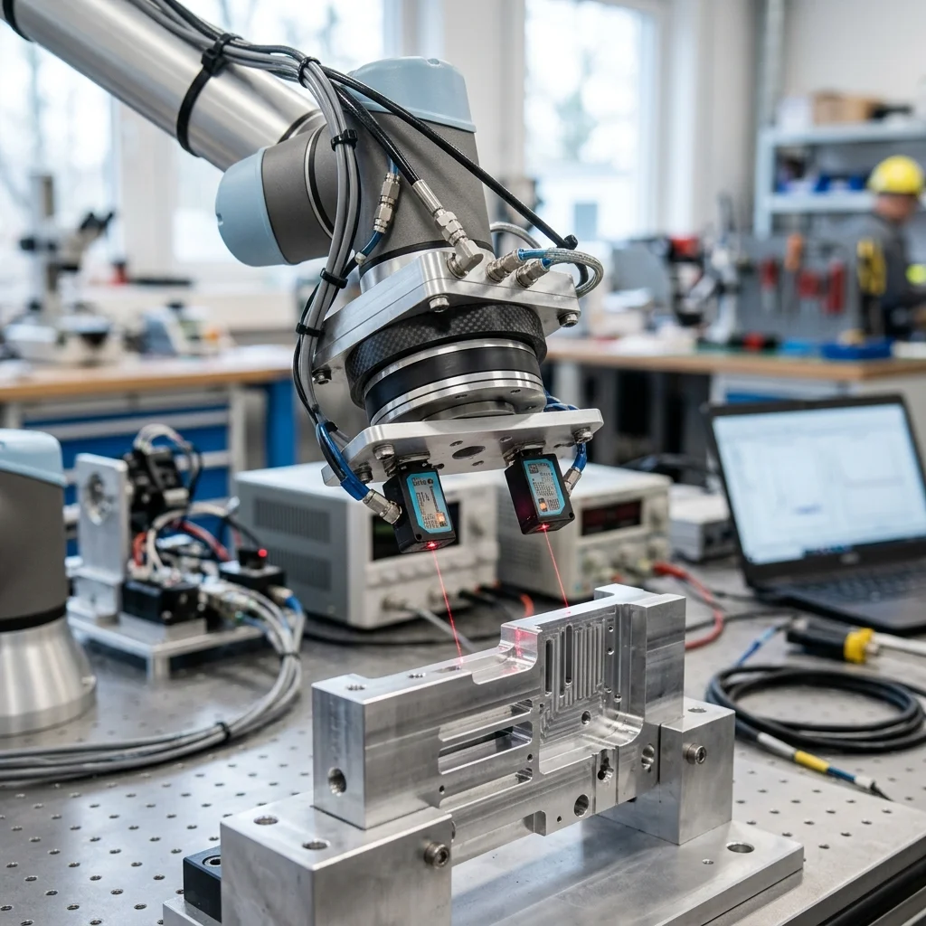
In addition to active control, passive compliance devices like remote center compliance (RCC) tools can be integrated. An RCC unit sits between the Quill and the gripper, allowing the tool to shift slightly in the X-Y plane under contact forces. This mechanical float aligns the part with the hole naturally, reducing the processing load on the control system.
Vacuum End-Effector Integration and Part Detection
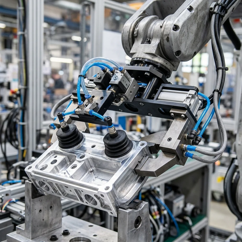
For high-speed pick-and-place, vacuum cups are the most common end effector. The system must verify that a part has been successfully grasped before moving to the deposit location. This is achieved by integrating digital vacuum switches directly into the pneumatic lines, which monitor the vacuum level (measured in negative pressure, like -70 kPa).
If a part is missed or dropped, the vacuum switch detects the pressure loss, and the controller halts the program immediately, displaying a fault message. This prevents the robot from executing a dry cycle and placing a non-existent part. The vacuum lines should be kept short to minimize the time required to build and release pressure.
Blow-off circuits must also be integrated. After the robot places a part, a brief pulse of positive compressed air is directed to the suction cup. This positive pressure breaks the vacuum instantly, allowing the robot to lift away without dragging the part along. Tuning the duration of this blow-off pulse is critical to prevent shifting the component on the board.
SCARA Commissioning and Speed Tuning Checklist
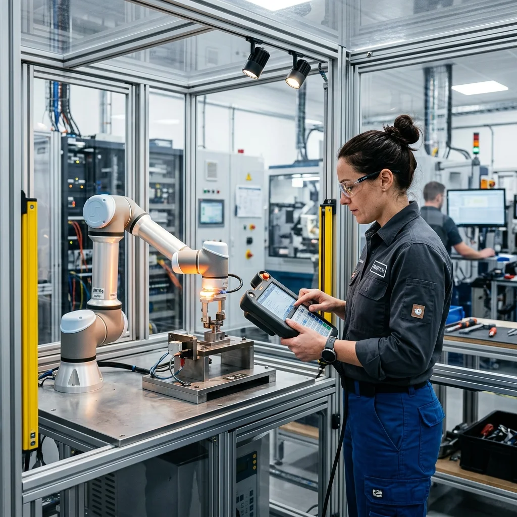
Before running production at 100% speed, the mechatronics team must run through a commissioning checklist. First, verify that the mounting pedestal is rigid and bolted securely to the floor, as pedestal flex will cause path errors. Second, run the robot through its cycle at 10% speed, verifying that the tool clears all obstacles with safe margins.
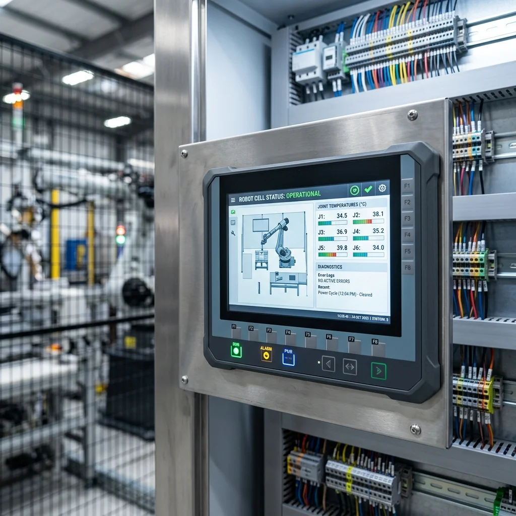
Third, optimize the Arch parameters to minimize vertical travel while maintaining clearance. Fourth, verify that the vacuum sensor reliably detects missed parts during testing. Finally, monitor the motor temperatures during a continuous test run to ensure they remain within safe operating limits, preventing thermal overload.